Just to cut short the length of the article i decided to break the making of Moodles- An interactive lamp into several parts in this way anyone can follow various modules in a step-wise fashion.
In this post i am gonna discuss making RGB connection with arduino board and write code for fading it.Nothing fancy here but it's preliminary to next step of making RGB fade with music beats.If you can work your way around one LED you can do same for the array for LEDs or make a matrix of them and control the load at arduino i/o ports.
In this post i am gonna discuss making RGB connection with arduino board and write code for fading it.Nothing fancy here but it's preliminary to next step of making RGB fade with music beats.If you can work your way around one LED you can do same for the array for LEDs or make a matrix of them and control the load at arduino i/o ports.
Hardware
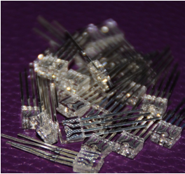
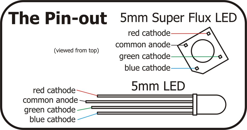
The hardware part in this project is a simple RGB LED. I am using 4-leged flat head 5mm RGB LED common anode .
Specifications:-
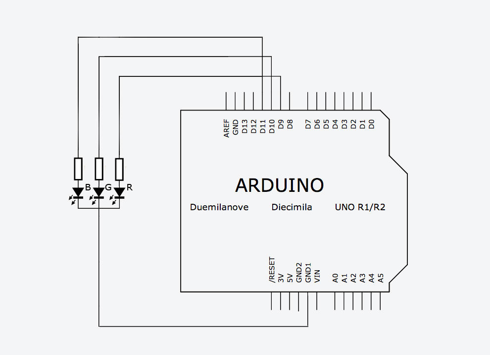
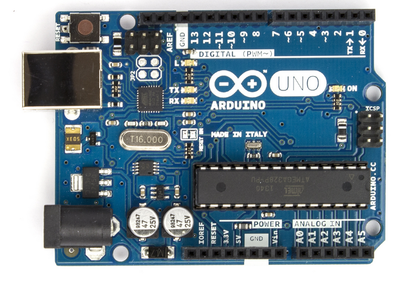
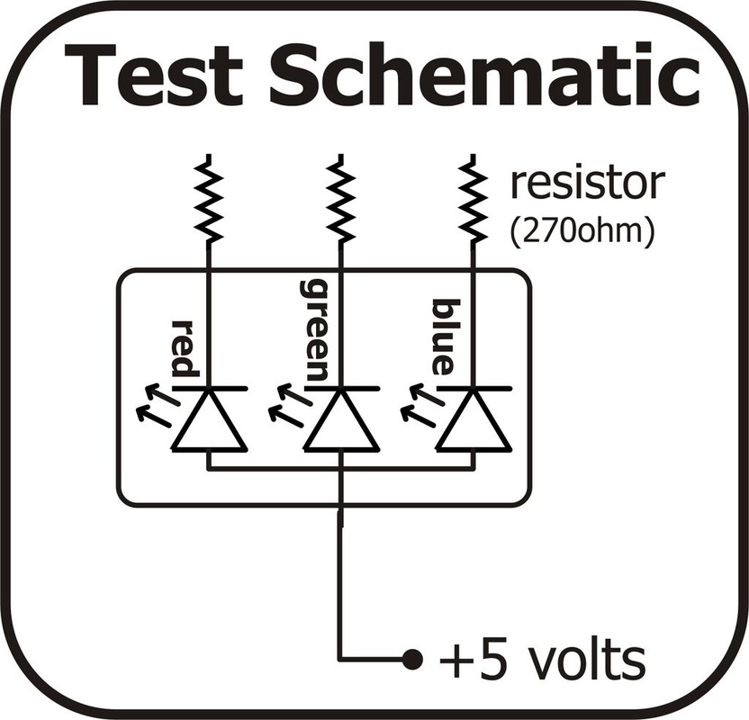
While tinkering with the RGB i figured out that i was using common anode RGB Led so it's wiring will be little different from that of common cathode.The 4-leged LED with the longest leg is our common anode and we will be connecting it to +5V power supply from our Arduino board.Rest all legs are different colours(Red,Blue and Green) for each colour there is different value of resistance(200-330 ohms) required.There will be three different resistors for each colour and one leg of resistor will be connected to the output pins on Arduino board(Generally they're 9,10 & 11).
Follow this simple rule in case you get confused in common anode and common cathode led wiring:
Specifications:-
- Max reverse current:20mA
- RGB LED 5mm
- Max Forward Voltage :3.0V-3.4V
- Max Forward Current : 20mA
- Supply Voltage :5V (From Arduino board)
While tinkering with the RGB i figured out that i was using common anode RGB Led so it's wiring will be little different from that of common cathode.The 4-leged LED with the longest leg is our common anode and we will be connecting it to +5V power supply from our Arduino board.Rest all legs are different colours(Red,Blue and Green) for each colour there is different value of resistance(200-330 ohms) required.There will be three different resistors for each colour and one leg of resistor will be connected to the output pins on Arduino board(Generally they're 9,10 & 11).
Follow this simple rule in case you get confused in common anode and common cathode led wiring:
- A RGB Common Anode LED should have it's longest leg (leg 2) connected to the 5V pin on your Arduino (Current sink)
- A RGB Common Cathode LED should have it's longest leg (leg 2) connected to the ground pin on your Arduino (Current source)
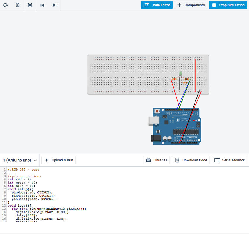
//RGB LED - test
//pin connections
int red = 9;
int green = 10;
int blue = 11;
void setup()
{
pinMode(red, OUTPUT);
pinMode(blue, OUTPUT);
pinMode(green, OUTPUT);
}
void loop()
{
for (int pinNum=9;pinNum<12;pinNum++)
{
digitalWrite(pinNum, HIGH);
delay(500);
digitalWrite(pinNum, LOW);
delay(500);
}
}
//pin connections
int red = 9;
int green = 10;
int blue = 11;
void setup()
{
pinMode(red, OUTPUT);
pinMode(blue, OUTPUT);
pinMode(green, OUTPUT);
}
void loop()
{
for (int pinNum=9;pinNum<12;pinNum++)
{
digitalWrite(pinNum, HIGH);
delay(500);
digitalWrite(pinNum, LOW);
delay(500);
}
}
Schematics
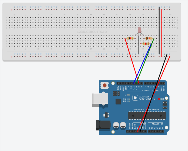
This simulation was made using 123D circuits https://123d.circuits.io/
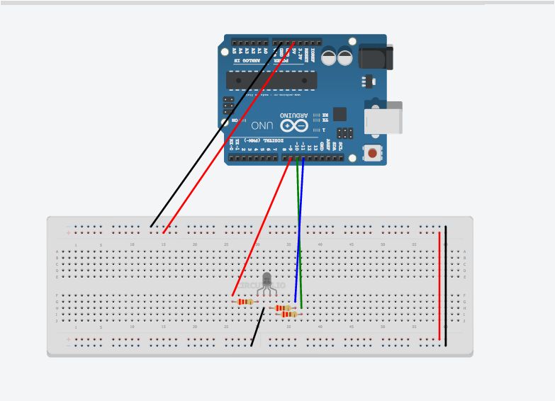
PWM: 3, 5, 6, 9, 10, and 11 are available to us on are Arduino uno board and provide 8-bit PWM output with the analogWrite() function.I'm using pins 9,10 and 11. Using the PWN pins and analogWrite() allows access to wide spectrum of colours.
Now im going to include analogWrite() and Random() to set a random brightness levels for each of the colours in the LED. The three colours will mix in different proportions (depending on their brightness) to make a wide variety of colours (255^3 = 16,581,375 possible colours).
random(256); //returns a number between 0 and 255
//RGB LED - random colours
//pin connections
int red = 9;
int green = 10;
int blue = 11;
void setup(){
pinMode(red, OUTPUT);
pinMode(blue, OUTPUT);
pinMode(green, OUTPUT);
}
void loop(){
//pick a random colour
analogWrite(red,random(256));
analogWrite(blue,random(256));
analogWrite(green,random(256));
delay(1000); //wait one second
}
---------------------------------------------------------------------------------------------------------------
The following sketch fades LED from red to green to blue to red to green and so on...
//RGB LED - random colours with diffusing colours
//pin connections
int red = 9;
int green = 10;
int blue = 11;
int brightness=0;
void setup(){
pinMode(red, OUTPUT);
pinMode(blue, OUTPUT);
pinMode(green, OUTPUT);
}
void loop(){
for(brightness=0;brightness<256;brightness++){
analogWrite(red,255-brightness);
analogWrite(green,brightness);
delay(10);
}
for(brightness=0;brightness<256;brightness++){
analogWrite(green,255-brightness);
analogWrite(blue,brightness);
delay(10);
}
for(brightness=0;brightness<256;brightness++){
analogWrite(blue,255-brightness);
analogWrite(red,brightness);
delay(10);
}
}
NOTE: The code above is quite repetitive so we will make few changes and bring all the functionality of the above repetitive code into one fader code.
//RGB LED- fading between colours
//pin connections
int red=9;
int green =10;
int blue =11;
void setup() {
pinMode(red, OUTPUT);
pinMode(green, OUTPUT);
pinMode(blue, OUTPUT);
}
void loop() {
fader(red,green);
fader(green,blue);
fader(blue,red);
}
void fader(int colour1, int colour2){
for(int brightness=0;brightness<256;brightness++){
analogWrite(colour1,255-brightness);
analogWrite(colour2,brightness);
delay(10);
}
}
Explaining code written above:-
Let's follow line by line for the snippet
void fader(int colour1, int colour2){
for (int brightness=0;brightness<256;brightness++){
analogWrite(color1, 255-brightness);
analogWrite(color2, brightness);
delay(10);
}
}
The function is called "fader" and it takes two arguments. Each argument is separated by a comma and has a type declared in the first line of the function definition:
void fader(int colour1, int colour2)
We can see that both of the arguments fader accepts are ints, and we're using the names "colour1" and "colour2" as dummy variables for our function definition. The "void" refers to the data type that the function returns, since our function does not return anything (it simply executes commands), we set the return type to void.
fader(red, green);
from the Arduino's loop(), the Arduino evaluates the fader function with colour1 = red and colour2 = green.
//pin connections
int red = 9;
int green = 10;
int blue = 11;
void setup(){
pinMode(red, OUTPUT);
pinMode(blue, OUTPUT);
pinMode(green, OUTPUT);
}
void loop(){
//pick a random colour
analogWrite(red,random(256));
analogWrite(blue,random(256));
analogWrite(green,random(256));
delay(1000); //wait one second
}
---------------------------------------------------------------------------------------------------------------
The following sketch fades LED from red to green to blue to red to green and so on...
//RGB LED - random colours with diffusing colours
//pin connections
int red = 9;
int green = 10;
int blue = 11;
int brightness=0;
void setup(){
pinMode(red, OUTPUT);
pinMode(blue, OUTPUT);
pinMode(green, OUTPUT);
}
void loop(){
for(brightness=0;brightness<256;brightness++){
analogWrite(red,255-brightness);
analogWrite(green,brightness);
delay(10);
}
for(brightness=0;brightness<256;brightness++){
analogWrite(green,255-brightness);
analogWrite(blue,brightness);
delay(10);
}
for(brightness=0;brightness<256;brightness++){
analogWrite(blue,255-brightness);
analogWrite(red,brightness);
delay(10);
}
}
NOTE: The code above is quite repetitive so we will make few changes and bring all the functionality of the above repetitive code into one fader code.
//RGB LED- fading between colours
//pin connections
int red=9;
int green =10;
int blue =11;
void setup() {
pinMode(red, OUTPUT);
pinMode(green, OUTPUT);
pinMode(blue, OUTPUT);
}
void loop() {
fader(red,green);
fader(green,blue);
fader(blue,red);
}
void fader(int colour1, int colour2){
for(int brightness=0;brightness<256;brightness++){
analogWrite(colour1,255-brightness);
analogWrite(colour2,brightness);
delay(10);
}
}
Explaining code written above:-
Let's follow line by line for the snippet
void fader(int colour1, int colour2){
for (int brightness=0;brightness<256;brightness++){
analogWrite(color1, 255-brightness);
analogWrite(color2, brightness);
delay(10);
}
}
The function is called "fader" and it takes two arguments. Each argument is separated by a comma and has a type declared in the first line of the function definition:
void fader(int colour1, int colour2)
We can see that both of the arguments fader accepts are ints, and we're using the names "colour1" and "colour2" as dummy variables for our function definition. The "void" refers to the data type that the function returns, since our function does not return anything (it simply executes commands), we set the return type to void.
fader(red, green);
from the Arduino's loop(), the Arduino evaluates the fader function with colour1 = red and colour2 = green.
Resource
Wanna try more ??
http://hackaday.com/2012/09/08/hacking-a-floating-rgb-led-decorative-ball/
- http://www.instructables.com/id/Choosing-The-Resistor-To-Use-With-LEDs/
- http://www.robotroom.com/Calculators/Resistor/Resistor-Color-Code-Calculator.aspx
- http://www.instructables.com/id/RGB-LED-Tutorial-using-an-Arduino-RGBL/?ALLSTEPS
- http://wiring.org.co/learning/basics/rgbled.html
Wanna try more ??
http://hackaday.com/2012/09/08/hacking-a-floating-rgb-led-decorative-ball/
WARNING !!
Important: don't fry your Arduino and/or your USB port!!
Never make a circuit that demands a current greater than 50mA in each port. It could fry your Arduino and/or the USB of your computer.
Never change the wiring of the circuit while connected to USB and/or to an external source.
Never make a circuit that demands a current greater than 50mA in each port. It could fry your Arduino and/or the USB of your computer.
Never change the wiring of the circuit while connected to USB and/or to an external source.
 RSS Feed
